The triode as vacuum tube is one of the most used active element in audio amplifier circuits. The low power dissipation triode tubes are used in pre-amplifier applications, but there are also high power triode tubes which can be used in output power amplifier stages. The basic functionality of the triode as active element may be described as an electron flow from the cathode to the plate established by the plate to cathode voltage Vpk, whose flow rate is controlled by the grid to cathode voltage Vgk as it, if negative, “pushes back” electrons towards the cathode. The modeling of triode tube can be implemented on many different ways. The model can be simple or complex, depending of the approach. For instance, the model can include the effect of space current saturation and filament voltage. The simpler models have a lack of the description of the important tube phenomena and therefore they are unable to give the realistic distortion results. The triode model is based on the equations shown on Picture 1.

Picture 1: Triode Model Equations
The plate (anode) current Ia is determined with the first equation. Here, the G parameter is the tube perveance at zero bias, the Mu parameter is the tube amplification factor, Vg is the grid voltage and Va is the plate (anode) voltage. The second equation is for the grid current Ig. The G and Mu parameters are the constants determined by the particular tube. Also and the parameters vB, vC, vD, alpha and beta are the characteristics determined by the particular tube.
The vacuum tubes have a sound shaping phenomena which makes them unique in the audio signal processing. Clearly, the non-linear behavior of the plate current is the primary source of signal distortion, but for large input signals, which force Vgk to become positive, the diode between the grid and the cathode introduces distortion as well. Furthermore, the grid current emerging for positive Vgk charges the input capacitor in amplifier circuit application, involving a shift of the operating point and causing blocking distortion. Regarding the cathode circuit, as the cathode current varies at the rate of the input signal and the low-pass consisting of the parallel combination of the cathode resistor and capacitor, Rk and Ck, can not completely remove the AC component, which occurs a feedback to the input. Finally, the parasitic capacitances of the tube depicted in involve additional filtering, where the Miller effect deserves a special notice. So, all in all, modeling the tube is not so simple in general, since there a lot of parameters included in non-linear relations. The goal here, is to reduce the number of non-linearities at the price of a coarse approximation and making the wave digital structure a time varying function block which will reflect the closest characteristics to the real tube. Using the equations like those above, and also considering many other equations and approximations which describes the tube behavior, we can make a model of a triode tube as the one shown on the Picture 2.
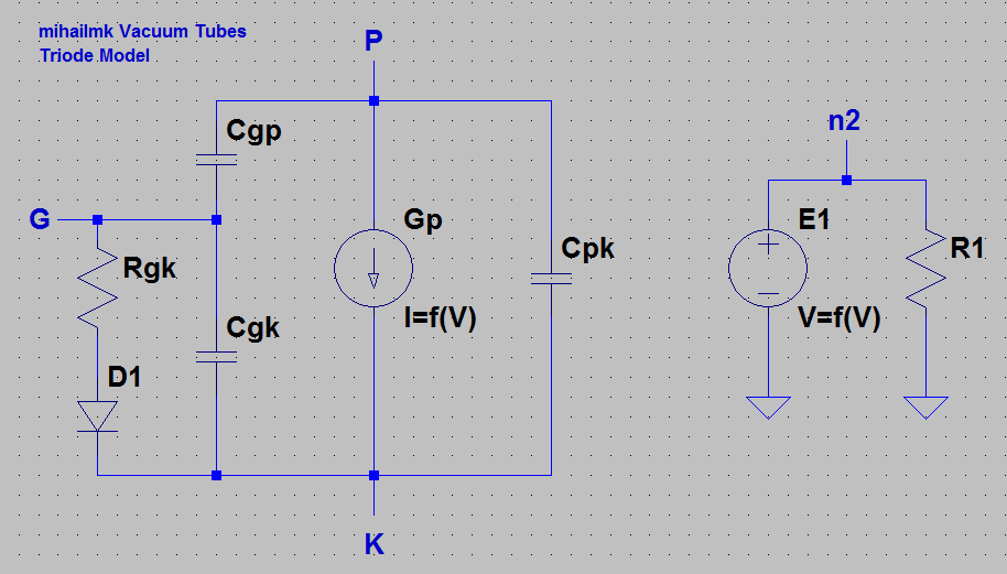
Picture 2: The Triode Vacuum Tube Model Circuit
Here, the P, G and K nodes, are actually the three electrodes of the triode tube, the Plate (anode) the grid and the cathode. The plate current is modeled as voltage controlled current source Gp. The capacitors Cgp, Cgk and Cpk are the parasitic capacitances of the tube between its electrodes, respectively. E1 is the internal voltage controlled voltage source in parallel combination with the resistor R1. A series of a solid-state diode D1 and the resistor Rgk approximately model the grid circuit for Vgk > 0. This approach is to represent the grid to cathode path asa switched resistor Rgk, which for the voltage of Vgk > 0 is about 2.7 kOhms, and for Vgk < 0 it has a large value of about 100 GOhms and in this case the diode D1 is off, so no current flows through this circuit path.
The ECC83 subcircuit model for LT Spice
According to the model circuit for triode tube shown on the Picture 2, we created a subcircuit model for the ECC83 or 12AX7 vacuum tube triode. The parameters values used in this model are from the ECC83 triode manufactured by JJ Electronic. The plate dissipation of this triode is 1W. The amplification factor Mu is equal to 100. The parasitic capacitances of the triode are Cgk = 1.6 pF, Cgp = 1.7 pF and Cpk = 0.33 pF. The connections for the subcircuit are Plate at node 1, Grid at node 2 and Cathode at node 3. This subcircuit can be used with already existing triode symbol in LT Spice, since the connection assignments are corresponding to the symbol. If you want to use this subcircuit with the LT Spice triode symbol you will need just to enter this subcircuit file (.sub) as symbol attribute into the symbol file (.asy) for the triode tube.
The ECC83.sub file:
* Copyright © Mihail Electronics & Music ltd. 2010 All rights reserved.
* ECC83 or 12AX7 Triode (JJ Electronic)
* Plate dissipation 1W;
* Amplification factor Mu = 100;
* Cgk = 1.6 pF; Cgp = 1.7 pF; Cpk = 0.33 pF;
* Connections: Plate
* | Grid
* | | Cathode
* | | |
.SUBCKT ECC83 1 2 3
E1 n2 0 VALUE = {V(1,3) + 100*V(2,3)}
R1 n2 0 1K
G1 1 3 VALUE = {1.73E-6*(PWR(V(n2),1.5) + PWRS(V(n2),1.5))/2}
R2 2 n1 2.7K
D1 n1 3 DM
C1 1 2 1.7PF
C2 2 3 1.6PF
C3 1 3 0.33PF
.MODEL DM D
.ENDS
No comments:
Post a Comment