Technical controllers are a component part of automation systems, whose main task is that of process stabilisation. They are used with the aim of:
>> bringing about and maintaining specific process states (mode of operation) automatically;
>> eliminating the effects of interference on the process sequence;
>> preventing unwanted coupling of part processes in the technical process.
The process states addressed primarily refer to specific process parameters, such as pressure, flow, temperature, filling level and quality (pH value).
Mode of operation of closed control loop
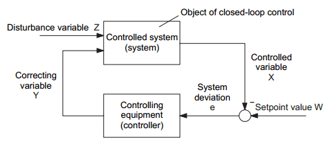
Picture 1 shows the basic structure of a closed control loop. Its mode of operation can be described as follows:
Picture 1: Mode of operation of closed control loop
The required value of the controlled variable X, i. e. its desired characteristic as a function of time, is specified by the setpoint value W. This can be done manually on the control equipment of the controller or also by a controlling device, which is of higher-order to the controller. In the case of a fixed setpoint value, we talk of a fixed setpoint control, and in the case of a time varying setpoint value of a setpoint control or servo control. The controlled variable X is continually measured via a suitable measuring device (or at permissible time intervals) and compared with the setpoint value W by means of subtraction.
The system deviation e = W - X indicates, how much and in which direction (e. g. valve to be opened or closed more) intervention in the process is necessary via the correcting variable Y in order to eliminate the occurring system deviation. The controlling device is used as an information processing system, which calculates the correcting variable Y appropriate for the control process from the existing system deviation.
Technical controlled systems are subject to a multitude of interference (load variations, changes in the quality of materials used, etc.). To simplify matters, Picture 1 therefore only includes one main disturbance variable Z. All disturbances have an effect on the controlled variable and change (e. g. in the case of a fixed setpoint control) its required operating point value Xo = Wo. As such, all disturbances are therefore reflected in the system deviation, and the above described control process, which is carried out continually and automatically, then ensures as complete a diminution of the system deviation as possible and thus the elimination of the effect of the disturbance on the controlled variable.
The success of a control system obviously depends critically on the time-related characteristic of the disturbance variables (and time varying setpoint values), the steady-state and dynamic behaviour of the controlled system and information processing in the controlling equipment.
Steady-state behaviour of the closed control loop
Similar to the deliberations regarding the simulation of the steady and dynamic behaviour of the technical system to be controlled (in this case controlled systems), it is also essential to discuss the concepts and descriptions regarding the steady-state and dynamic behaviour of closed control loops.
The description of the steady-state closed control loop behaviour again entails the use of characteristic curves or characteristics, in this case, the steady-state models of controlled system and controller. Hence Picture 2 (a) illustrates the steady-state characteristic of the controlled system and Picture 2 (b) the steady-state characteristic of a proportionally acting controller. Here, Y designates the correcting variable (e. g. valve position) and X the controlled variable (e. g. temperature).
Picture 2: Performance characteristic of: (a) controlled system (b) controlled device
Both characteristics can be represented jointly if identical scaling is selected (Picture 3). The interface between the valid characteristics for the controlled system (Z = Z0) and the controlling equipment (W = W0) result in the operating point Ao and hence the operating point values Y0 or X0 for the actuating signal Y or for the controlled variable signal X. If the interference then changes from Z = Z0 to Z = Z1, then, in the case if a fixed valve position Y0 (to remain with the example), i.e. with a controller which is switched off or has not been started up, the operating point would drift from A0 to A1 and the controlled variable X (e. g. the temperature) would assume the value X1 .
However, if the controller is active then, on the basis of the same considerations which apply to the interface A0, the operating point A2 occurs, since the now operative characteristic curves of the controlled system for Z= Z1 and of the controlling device for W = W0 (with unchanged setpoint value) now need to be intersected. The operating point in this case therefore drifts from A0 to A2. The corresponding operating point values are Y2 and X2. In order to prevent the unwanted increase of the controlled variable from X0 to X1 at least to some extent, the setpoint value is reset via the controller from Y0 to Y2 and the steady-state controlled variable value X2 set.
The flatter the form of the characteristic curve of the controller in Picture 3, the more effective the controller probably is with regard to the steady-state behaviour of the closed control loop. In the borderline case of a horizontally running controller characteristic curve, the control objective of complete diminution of the stationary system deviation es = W0 - X2, could even be completely achieved. However, a horizontally running controller characteristic curve as shown in Picture 3 means a vertical pattern in Picture 2 (b), and as such an infinitely high proportional coefficient of the controller assumed to be of proportional action. That this optimum steady-state closed control loop behaviour can actually be realised, can only be seen by further pursuing deliberation regarding information processing in technical controllers.
Picture 3: Steady-state performance characteristics of closed control loop, Interference changes from Z0 to Z1:
1. Working point variation with fixed setpoint value Y0
2. Working point variation with active closed-loop control


No comments:
Post a Comment